


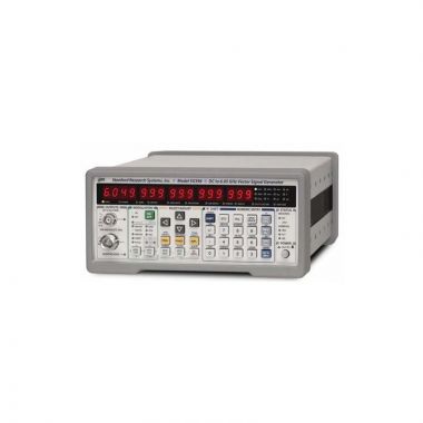
SRS SG396 6 GHz RF Vector Signal Generator
Please contact us for estimated delivery

- DC to 2 GHz, 4 GHz or 6 GHz
- Dual baseband arb generators
- Vector and analog modulation
- I/Q modulation inputs (300 MHz RF BW)
- ASK, FSK, MSK, PSK, QAM, VSB and custom I/Q
- Presets for GSM, EDGE, W-CDMA, APCO-25, DECT, NADC, PDC, ATSCDTV & TETRA
- GPIB, RS-232 & Ethernet interfaces
Lambda Exclusive Promotion:
Additional 12 months warranty for free (2 years total) via our UK Service Centre.
Three new Stanford Research Systems RF Signal Generators, with carrier frequencies from DC to 2.025 GHz, 4.050 GHz and 6.075 GHz, support both analogue and vector modulation. The instruments utilise a new RF synthesis technique which provides spur free outputs with low phase noise (–116 dBc/Hz at 1 GHz) and extraordinary frequency resolution (1 μHz at any frequency). Both analogue modulation and vector baseband generators are included as standard features.
The instruments use an ovenised SC-cut oscillator as the standard time base, providing a 100 fold improvement in the stability (and a 100 fold reduction in the in-close phase noise) compared to instruments which use a TCXO time base.
A New Frequency Synthesis Technique
The SRS SG390 Series Signal Generators are based on a new frequency synthesis technique called Rational Approximation Frequency Synthesis (RAFS). RAFS uses small integer divisors in a conventional phase-locked loop (PLL) to synthesize a frequency that would be close to the desired frequency (typically within ±100 ppm) using the nominal PLL reference frequency. The PLL reference frequency, which is sourced by a voltage controlled crystal oscillator that is phase locked to a dithered direct digital synthesizer, is adjusted so that the PLL generates the exact frequency. Doing so provides a high phase comparison frequency (typically 25 MHz) yielding low phase noise while moving the PLL reference spurs far from the carrier where they can be easily removed. The end result is an agile RF source with low phase noise, essentially infinite frequency resolution, without the spurs of fractional-N synthesis or the cost of a YIG oscillator.
Analogue Modulation
The SG390 Signal Generators offer a wide variety of modulation capabilities. Modes include amplitude modulation (AM), frequency modulation (FM), phase modulation (ΦM), and pulse modulation. There is an internal modulation source as well as an external modulation input. The internal modulation source produces sine, ramp, saw, square, and noise waveforms. An external modulation signal may be applied to the rear-panel modulation input. The internal modulation generator is available as an output on the rear panel.
Unlike traditional analogue signal generators, the SG390 Series can sweep continuously from DC to 62.5 MHz. And for frequencies above 62.5 MHz, each sweep range covers more than an octave.
Vector Modulation
The SG390 series builds upon this performance by adding full support for vector signal modulation on RF carriers between 400 MHz and 6.075 GHz. It features a dual, arbitrary waveform generator operating at 125 MHz for baseband signal generation. The generator has built-in support for the most common vector modulation schemes: ASK, QPSK, DQPSK, π/4 DQPSK, 8PSK, FSK, CPM. QAM (4 to 256), 8VSB, and 16VSB. It also includes built-in support for all the standard pulse shaping filters used in digital communications: raised cosine, root-raised cosine, Gaussian, rectangular, triangular, and more. Lastly, it provides direct support for the controlled injection of additive white Gaussian noise (AWGN) into the signal path.
Internal Baseband Generators
Using a novel architecture for I/Q modulation, the SG390 series provides quick, user-friendly waveform generation. The baseband generator supports the playback of pure digital data. It automatically maps digital symbols into a selected I/Q constellation at symbol rates of up to 6 MHz and passes the result through the selected pulse shaping filter to generate a final waveform updated in real time at 125 MHz. This baseband signal is then modulated onto an RF carrier using standard IQ modulation techniques.
Preset communications protocols (GSM, GSM EDGE, W-CDMA, APCO-25, DECT, NADC, PDC, TETRA, and ATSC DTV) quickly configure the signal generator to the correct modulation type, symbol data rates, TDMA duty cycles and digital waveform filters. The preset protocols also configure the rear-panel TDMA, START of FRAME, and SYMBOL CLOCK digital outputs. The baseband generators can be configured for these protocols without the use of external computers or third party software.
The I/Q waveforms are computed in real time. Symbols are mapped to constellations, digitally filtered, and up-sampled to 125 Msps to drive the I/Q modulator via dual 14-bit DACs. The symbols can be a fixed pattern, PRBS data from an internal source, or come from a downloaded user list of up to 16 Mbits. The constellation mapping can be modified by the user. Digital filters include Nyquist, root Nyquist, Gaussian, rectangular, linear, sinc, and user-defined FIR.
External I/Q Modulation
The rear-panel BNC I/Q modulation inputs and outputs enable arbitrary vector modulation via an external source. The external signal path supports more than 300 MHz of bandwidth with a full scale range of ±0.5 V and a 50 Ω input impedance.
Power vs Frequency
All SRS RF signal generators have cascaded stages of amplifiers and digital attenuators to drive the RF output. Five stages can provide up to +25 dB of gain to -130 dB of attenuation in 156 digitally controlled steps. During factory calibration the output power is measured at 32 frequencies per octave for each of the 156 attenuator steps to populate a memory matrix with about 40,000 elements. When set to a particular frequency and power, the instrument interpolates between these matrix elements to determine the best attenuator setting. An analogue attenuator is used to provide 0.01 dB resolution between matrix elements and to compensate for residual thermal effects. This method eliminates the need for precision attenuators and automatic level controls (ALC) without any sacrifice in performance. Eliminating the ALC also removes its unwanted interactions with amplitude, pulse and I/Q modulation.
OCXO or Rubidium Timebase
The SG390 Series come with a oven-controlled crystal oscillator (OCXO) timebase. The timebase uses a third-overtone stress-compensated 10 MHz resonator in a thermostatically controlled oven. The timebase provides very low phase noise and very low aging. An optional rubidium oscillator (Opt. 04) may be ordered to substantially reduce frequency aging and improve temperature stability. An external 10 MHz timebase reference may be supplied to the rear-panel timebase input.
Easy Communication
Remote operation is supported with GPIB, RS-232 and Ethernet interfaces. All instrument functions can be controlled and read over any of the interfaces. Up to nine instrument configurations can be saved in non-volatile memory.
|
SG390 Series Vector Specifications |
|
|
External I/Q Modulation |
|
|
Carrier frequency range |
|
|
SG392 |
400 MHz to 2.025 GHz |
|
SG394 |
400 MHz to 4.05 GHz |
|
SG396 |
400 MHz to 6.075 GHz |
|
I/Q inputs |
50 Ω, ±0.5 V (rear panel) |
|
I/Q full scale input |
√(I2 + Q2) = 0.5 V |
|
Modulation bandwidth |
300 MHz RF bandwidth |
|
I or Q input offset |
<500 µV |
|
Carrier suppression |
>40 dBc (>35 dBc above 4 GHz) |
|
Dual Baseband Generator (for Vector I/Q Modulation) |
|
|
Channels |
2 (I and Q) |
|
DAC data format |
Dual 14-bit at 125 MS/s |
|
Reconstruction filter |
10 MHz, 3rd order Bessel LPF |
|
Arb symbol memory |
Up to 16 Mbits |
|
Symbol rate |
1 Hz to 6 MHz (1 µHz resolution) |
|
Symbol length |
1 to 9 bits (maps to constellation) |
|
Symbol mapping |
Default or user-defined constellation |
|
Symbol source |
User-defined symbols, built-in PRBS generator, or settable pattern generator |
|
PRBS length |
2n - 1 (5<n<32) |
|
Pattern generator |
16 bits |
|
Digital filtering |
|
|
Filter type |
Nyquist, Root Nyquist, Gaussian, Rectangular, Linear, Sinc, User FIR |
|
Filter length |
24 symbols |
|
Noise impairments |
|
|
Additive noise |
White, Gaussian |
|
Level |
-70 dBc to -10 dBc (band limited by digital filter) |
|
Vector Modulation |
|
|
Modulation type |
PSK, QAM, FSK, CPM, MSK, ASK, VSB |
|
PSK derivatives |
PSK, BPSK, QPSK, OQPSK, DQPSK, π/4DQPSK, 8 PSK, 16 PSK, 3π/8 8 PSK |
|
QAM derivatives |
4, 16, 32, 64, 256 |
|
FSK derivatives |
1-bit to 4-bit with deviations from 0 to 6 MHz |
|
ASK derivatives |
1-bit to 4-bit |
|
CMP derivatives |
1-bit to 4-bit with modulation indices from 0 to 1.0 |
|
VSB derivatives |
8 and 16 (at rates to 12 MS/s) |
|
Preset modes |
GSM, GSM-EDGE, W-CDMA, APCO-25, DECT, NADC, PDC, TETRA, ATSC DTV, audio clip |
|
Rear-Panel Markers |
|
|
Type |
Symbol Clock, Data Frame, TDMA, and user-defined |
|
Amplitude |
0.5 to 4 Vpp (-2 dBm to +16 dBm) |
|
Output impedance |
50 Ω, AC coupled |
See Downloads for EVM or FSK Errors PDF for additional support.
![]() Stanford Research Systems SG390 Series datasheet
Stanford Research Systems SG390 Series datasheet
![]() Technical Overview of Four RF Signal Generators
Technical Overview of Four RF Signal Generators
![]() Why buying from Lambda makes sense
Why buying from Lambda makes sense
| Photo | Product | Price | |
|---|---|---|---|
 | SRS SG382 2 GHz RF Signal Generator | 4,742.00 | |
 | SRS SG392 2 GHz RF Vector Signal Generator | 7,804.00 | |
 | SRS SG384 4 GHz RF Signal Generator | 7,014.00 | |
 | SRS SG386 6 GHz RF Signal Generator | 8,100.00 | |
 | SRS SG394 4 GHz RF Vector Signal Generator | 8,792.00 |