SRS SR865A DSP Lock-In Amplifier, 4MHz
Please contact us for estimated delivery

- 1 mHz to 4 MHz
- Low noise voltage and current inputs
- 1 µs to 30 ks time constants
- High bandwidth outputs
- Touchscreen data display - large numeric results, chart recordings, & FFT displays
- 10 MHz timebase input and output
- GPIB, RS-232, Ethernet and USB
- HDMI video output
Lambda Exclusive Promotion:
Additional 12 months warranty for free (2 years total) via our UK Service Centre.
The new 4MHz SR865A Lock-in Amplifier is the latest in a line of innovative lock-ins from SRS. With unparalleled analogue performance, sophisticated new digital signal processing features, a modern, intuitive user interface, and a wide range of computer connectivity options, the SR865A is the ideal choice for any synchronous detection application.
With over 30 years design experience, SRS optimize each detail from a toroidal transformer that eliminates switch-mode noise, iOS mobile connectivity, to advanced DSP filters that eliminate more noise while speeding up your experiment, the SR865A is truly the ultimate lock-in amplifier.
Signal Inputs
Lock-in performance starts at the front end. The SR865A offers both state-of-the art voltage and current input amplifiers. The voltage input is a switchable single-ended/differential JFET-pair amplifier with 2.5nV/√Hz of noise at 1 kHz and under 10nV/√Hz of noise at 10Hz. The voltage input has a 10MΩ input impedance and can be AC or DC coupled. Input connector shields can be connected to the instrument ground through a user selectable 10Ω (Ground) or 10kΩ (Float) resistor.
The SR865A’s built-in current amplifier represents a significant improvement over previous designs. The current input range is selectable from 1μA or 10nA. The 1μA range has 400 kHz of bandwidth and 130 fA/√Hz of noise, while the 10nA range offers 2 kHz of bandwidth and 13 fA/√Hz of noise.
While the built in voltage and current amplifiers are suitable for most applications, the SR865A is also compatible with the complete range of specialized pre-amplifiers offered by SRS.
Sensitivity and Input Range
As with previous instruments, the Sensitivity setting of the SR865A is the voltage (or current) which produces a full scale output. But unlike previous designs, the input range of the SR865A can be set from the front panel without having to consult a confusing “dynamic reserve” equation. Simply choose the sensitivity required by your experiment and then select the smallest input range that doesn’t overload.
The SR865A’s effective dynamic reserve is simply the ratio of these two settings. E.g. a 10nV sensitivity setting and a 300mV input range the effective dynamic reserve of the SR865A is 3 × 10⁷, or nearly 150 dB.
Output Time Constants and Filtering
The SR865A offers traditional RC-response output time constants from 1µs to 30ks with rolloffs of 6, 12, 18, and 24dB/oct. In addition, advanced digital filters can significantly reduce measurement time. Synchronous filtering may be selected at reference frequencies below 4 kHz.
Reference Channel
The SR865A has a specified reference frequency range of 1mHz to 4MHz. Detection can be done at the fundamental of the reference frequency, or at up to the 99th harmonic. Several reference modes are available: Internal Mode, External mode, Dual Mode or Chop mode.
Sine Output
The SR865A offers a precision sine wave output which can be set with 6 digits of frequency resolution and from 1nV to 2V. The SR865A output is unique in that it can be configured as a single-ended or differential (balanced) signal. A DC offset of up to ±5 V can be applied to the sine output.
Timebase
Rear-panel 10 MHz inputs and outputs are provided allowing the SR865A to be locked to an external frequency reference (such as the FS725 10 MHz Rubidium Frequency Standard).
FFT Displays
Lock-in amplifiers are traditionally time-domain instruments but sometimes it’s easier to understand in the frequency domain. An FFT display shows the spectrum of the input signal, the post-mixer signal, or the spectrum of the signal after the time-constant filters.
Front-Panel Touchscreen Display
The centre of the SR865A’s front panel is a colour 640 × 480 touchscreen which can display up to 4 channels of data. Each data channel can be configured to display X, Y, R, Θ, Aux In (1-4), Aux Out (1-2), X noise, Y noise, Sine Amplitude, Sine Out DC Level, Reference Phase, or Reference Frequency. The screen can be set up to show the data channels as large numbers or as a “strip-chart” display showing a complete history of each channel with selectable time scales from 0.5 s/div to 2 days/div. The touchscreen continually displays key lock-in setup parameters such as phase, reference frequency, and sine amplitude.
All commonly used controls are controllable with dedicated front panel knobs or buttons. Infrequently accessed configuration settings, such as the TCP/IP settings and other communication settings, are accessed through menus shown on the touchscreen.
Computer Connectivity
GPIB, RS-232, USB (Test and Measurement Class) and Ethernet (VXI-11 and telnet) are fitted as standard. The SR865A hosts its own webserver allowing the instrument to be monitored and controlled remotely with just a browser. The SR865A can be controlled remotely from an iPhone. The front USB port allows data and screen-shots to a USB flash drive.
Additional Information
| Max. Frequency | 4MHz |
|---|---|
| Type | DSP |
| Signal Channel | |
| Voltage Inputs | Single-ended or differantial |
| Voltage input range | 10mV to 1V (peak) |
| Current input range | 1μA or 10nA (peak) |
| Max input | 1V (peak) or 1μA (peak) |
| Input impedance | |
| Voltage input | 10 MΩ + 25 pF, AC or DC coupled |
| Current input | 1 kΩ or 100 Ω to virtual ground |
| Gain accuracy | ±1% (<200kHz), ±2% (to 4MHz) Signal amplitude must be less than 30% of input range |
| Noise (rms) | 2.5nV/√Hz at 1kHz (10mV input range, typ.) |
| Harmonic detection | –80dB (100kHz), –60 dB (>100 kHz) |
| CMRR | 90dB to 1kHz (DC coupled),decreasing by 6dB/oct above 100kHz |
| Dynamic reserve | >120 dB |
| Reference Channel | |
| Frequency range | 0.001 Hz to 4MHz (specified) |
| Timebase | 10MHz In/Out (phase locks the internal frequency to other SR865As) |
| Input impedance | 1MΩ or 50Ω |
| Phase setting resolution | 360/2³² degrees |
| Phase noise | |
| Int. ref | <0.0001° rms at 1kHz (100ms, 12 dB/oct) |
| Ext. ref (typ) | <0.001° rms at 1kHz (100ms, 12 dB/oct) |
| Phase drift | <0.002°/°C below 20kHz (DC coupled) |
| <0.02°/°C below 200kHz | |
| <0.2°/°C below 4MHz | |
| Harmonic detection | Detect at N × fref (N<99 and (N × fref)<4MHz) |
| Dual F reference | Detect at fdual = abs(fint – fext) |
| Chopper reference | SR86A drives SR540 Chopper (via Aux Out 4) to lock the chopper to fint |
| Demodulator | |
| DC stability | Digital output values have no drift |
| Time constants | 1μs to 30k s |
| Low pass filters | Typical RC-type filters or Advanced FIR/BiQuad filters |
| Filter slope | 6, 12, 18 or 24 dB/oct rolloff |
| Synchronous filter | Available below 4kHz |
| Harmonic rejection | –80 dB |
| Low latency output | Rear-panel BlazeX output with <2 μs delay (plus LPF rise/fall times) |
| Internal Oscillator | |
| Frequency range | 0.001Hz to 4MHz (specified) |
| Frequency accuracy | 25 ppm + 30 μHz (with internal timebase) |
| External timebase | 10 MHz timebase input/output (on rear panel) |
| Frequency resolution | 6 digits or 0.1 mHz, whichever is greater |
| Sine Output | |
| Outputs | Single-ended or differential |
| Output impedance | 50Ω source |
| Amplitude | 1 nVrms to 2 Vrms (amplitude is differential into 50 Ω loads). Output is halved when using in single-ended mode. Output is doubled when driving a high impedance load. |
| Amplitude resolution | 3 digits or 1 nV, whichever is greater |
| DC offset | ±5 V, differential or common mode |
| Offset resolution | 3 digits or 0.1 mV, whichever is greater |
| Output limit | ±6 V, sum of DC offset and peak amplitude |
| Amplitude stability | 50 ppm/°C |
| Sync | Logic level sync on rear panel (via BlazeX output) |
| Distortion | <–80 dBc (f < 1 kHz) |
| Data | |
| Data channels | Four data channels are displayed and graphed (green, blue, yellow, orange) |
| Data sources | Each data channel can be assigned any of these data sources: X, Y, R, θ, Aux In 1 to 4, Aux Out 1 to 2, X noise, Y noise, Sine Out Amplitude, Sine Out DC level, reference phase, or fref. |
| Data history | All data sources are continually stored at all chart display time scales. The complete stored history of any data source can be displayed sat any time. |
| Offset | X, Y and R may be offset up to ±999% of the output scale |
| Expand | X, Y and R may be expanded by ×10 or ×100 |
| Data buffer | 1M point internal data storage. Store (X), (X and Y), (R and θ), or (X, Y, R and θ) at sample rates up to 1.25 MHz. This is in addition to the data histories for the chart display. |
| Scanning | One of the following parameters may be scanned: fint, Sine Out Amplitude, Sine Out DC Level, Aux Out 1 or 2 |
| Inputs and Outputs | |
| CH1 output | Proportional to X or R (±10V full scale thru 50Ω) |
| CH2 output | Proportional to X and Y (rear panel) (±10V full scale thru 50Ω) |
| X and Y outputs | Proportional to Y or θ (±10V full scale thru 50Ω) |
| BlazeX | Low latency ouput of X, ±2.5 V full scale or logic level reference sync output, either thru 50Ω |
| Aux outputs | 4 BNC D/A outputs, ±10.5V thru 50Ω, 1mV resolution |
| Aux inputs | 4 BNC A/D inputs, ±10.5V, 1 mV resolution, 1MΩ input |
| Trigger input | TTL input triggers storage into the internal data buffer |
| Monitor output | Analog output of the signal amplifier |
| HDMI | Video output to external monitor or TV (640×480, 60Hz) |
| Timebase I/O | 1 Vrms, 10 MHz clock to synchronise internal reference to other units |
|
General |
|
| Interfaces | GPIB (IEEE-488.2), RS-232, USB and Ethernet |
| USB flash | Front-panel slot for USB flash storage of screen shots and data |
| Preamp power | 9-pin D connector to power SRS preamps |
| Power | 60W, 100/120/220/240VAC, 50/60Hz |
| Dimensions | 17”×5.25”×17” (WHD) |
| Weight | 30 lbs. |
| Warranty | One year parts and labor on defects in materials and workmanship |
![]() Stanford Research Systems SR865A datasheet
Stanford Research Systems SR865A datasheet
![]() Stanford Research Systems SR865A user manual
Stanford Research Systems SR865A user manual
![]() Why buying from Lambda makes sense
Why buying from Lambda makes sense
| Photo | Product | Max. Frequency | Type | Price | |
|---|---|---|---|---|---|
 | SRS SR860 DSP Lock-in Amplifier, 500 kHz | 500kHz | DSP | 6,416.00 | |
 | DISCONTINUED SRS SR830 DSP Lock-in Amplifier, 102kHz | 100kHz | DSP | > | |
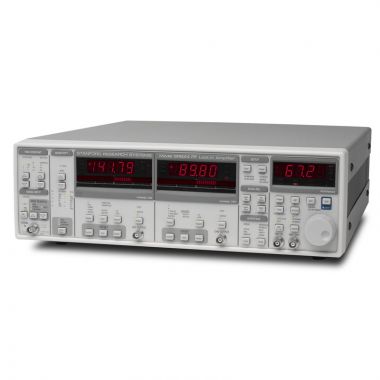 | SRS SR844 DSP RF Lock-in Amplifier, 200MHz | 200MHz | DSP | > | |
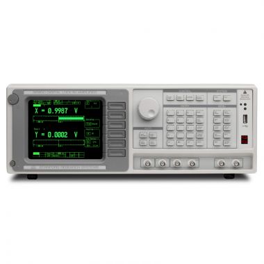 | SRS SR850 DSP Lock-in Amplifier, 102kHz | 100kHz | DSP | > | |
 | SRS SR2124 - 200 kHz Analogue/Analog Lock-in Amplifier | 200kHz | Analogue | > | |
 | SRS SX199 Optical Interface Controller | - | - | > | |
 | DISCONTINUED SRS SR530 Analogue Lock-in Amplifier, 100kHz | 100kHz | Analogue | > | |
 | SRS SR510 Analogue Lock-in Amplifier, 100kHz | 100kHz | Analogue | > |