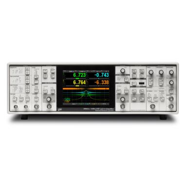
SRS SR844 DSP RF Lock-in Amplifier, 200MHz

- 25 kHz to 200 MHz frequency range
- >80 dB dynamic reserve
- Time constants from 100 µs to 30 ks (6, 12, 18 or 24 dB/oct rolloff)
- "No Time Constant" mode (10 to 20 µs update rate)
- Auto-gain, -phase, -reserve and -offset
- Internal or external reference
- Two 16-bit DACs and ADCs
- GPIB and RS-232 interfaces
Lambda Exclusive Promotion:
Additional 12 months warranty for free (2 years total) via our UK Service Centre.
The Stanford Research Systems SR844 is the widest bandwidth lock-in amplifier available. It provides uncompromised performance with a frequency range of 25 kHz to 200 MHz and up to 80 dB of drift-free dynamic reserve. The SRS SR844 includes the many features, ease of operation, and programmability that you've come to expect from SRS DSP lock-in amplifiers.
The SR844 uses the same advanced DSP technology found in the SR850, SR830 and SR810 lock-in amplifiers. DSP offers many advantages over analog instruments—high dynamic reserve, low zero-drift, accurate RF phase shifts and orthogonality, and digital output filtering.
Auto-functions allow parameters that are frequently adjusted to be set automatically. Sensitivity, dynamic reserve, phase and offset are each quickly optimized with a simple key stroke.
The offset and expand features are useful for evaluating small fluctuations in your signal. The input is nulled with the auto-offset function, and output expand increases the resolution by up to 100×.
Ratio mode is used to normalise the signal to an externally applied analog voltage. It is useful to eliminate the effect of source intensity fluctuations.
Transfer function measurements can be easily made from the front panel by a programmable scan of up to 11 frequencies. Setups and offsets are recalled at each frequency in the scan.
Inputs & Outputs
Analog Inputs and Outputs
The two displays each have a user-defined output for measuring X, Y, R, R(dBm), Θ, and X-noise or Y-noise. Two user-programmable DACs provide -10.5 V to +10.5 V outputs with 1 mV resolution. These outputs may be set from the front panel or via the computer interfaces.
In addition, there are two general purpose analog inputs. These are 16-bit ADCs which can be displayed on the front panel, read over the interface, or used to ratio the input signal.
Signal Input
The SR844 has both 50 Ω and 1 M Ω inputs. The 1 MΩ input is used with high source impedances at low frequencies, or with a standard 10× scope probe. The 50 Ω input provides the best RF signal matching. Full-scale sensitivities range from 1 Vrms (+13 dBm) down to 100 nVrms (-127 dBm). Up to 60 dB of RF attenuation or 20 dB of RF gain can be selected in 20 dB increments. Gain allocation can be optimized to provide up to 80 dB of dynamic reserve.
Reference
The SR844 offers both external and internal reference operation. In both cases, the entire 25 kHz to 200 MHz frequency range is covered without any manual range selection. The external reference input has an auto-threshold feature which locks to sine, square or pulsed signals. The internal reference is digitally synthesized and is adjustable with 3-digit frequency resolution.
Harmonic detection of the 2F component is available for both internal and external reference modes.
A reference output (1.0 Vpp square wave into 50 Ω) which is phase synchronous with the lock-in reference is available in both external and internal mode.
Output Filters
Time constants from 100 µs to 30 ks can be selected with a choice of 6, 12, 18 or 24 dB/oct rolloff. For high-bandwidth, real-time outputs, the filtering can be by-passed entirely. In this "No Filter" mode, the effective time constant is about 30 µs, with the analog outputs updating every 10 to 20 µs.
Ease of Operation
The SR844 is easy to use. All instrument functions are set from the front-panel keypad, and the knob is used to quickly adjust parameters. Up to nine different instrument configurations can be stored in non-volatile memory for fast, reliable instrument setup. Standard RS-232 and GPIB (IEEE-488.2) interfaces provide connections to your data acquisition systems.
Internal Memory
The SR844 has two 16,000 point memory buffers for recording the time history of each measurement display at rates up to 512 samples/s. Data may be transferred from the buffers using either interface. A trigger input is also provided to synchronize data recording with external events.
Additional Information
| Max. Frequency | 200MHz |
|---|---|
| Type | DSP |
| Signal Channel | |
| Voltage inputs | Single-ended BNC |
| Input impedance | 50 Ω or 1 MΩ + 30 pF |
| Damage threshold | ±5 V (DC + AC) |
| Bandwidth | 25 kHz to 200 MHz |
| Sensitivity: < 1 MHz < 50 MHz < 200 MHz |
100 nVrms to 1 Vrms full scale 1µVrms to 1 Vrms full scale 10 µVrms to 1 Vrms full scale |
| Gain accuracy: < 50 MHz < 200 MHz |
± 0.25 dB ± 0.50 dB |
| Gain stability | 0.2 %/°C |
| Coherent pickup | Low-noise reserve, sens. <30mV |
| f < 10 MHz | <100 nV (typ.) |
| f < 50 MHz | <2.5µV (typ.) |
| f < 200 MHz | <25µV (typ.) |
| Input noise (50 Ω) | 2 nV/√ Hz (typ.), 8 nV/√Hz (max.) |
| Input noise (1 MΩ), | 5 nV/√Hz (typ.), 8 nV/√Hz (max.) |
| Dynamic reserve | up to 80 dB |
| Reference Channel | |
| External reference input | 25 kHz to 200 MHz |
| Impedance | 50 Ω or 10 kΩ + 40 pF |
| Level | 0.7 Vpp pulse or 0 dBm sine |
| Pulse width | >2 ns at any frequency |
| Threshold setting | Automatic, midpoint of waveform |
|
Acquisition time
|
10s auto ranging any frequency 1s within same octave |
| Internal reference | 25 kHz to 200 MHz) |
| Frequency resolution | 3 digits |
| Frequency accuracy | ±0.1 in the 3rd digit |
| Harmonic detection | 2F (50 kHz to 200 MHz) |
| Reference outputs | Phase locked to Int. or Ext. reference |
| Front panel ref output | 25 kHz to 200 MHz square wave, 1.0 Vpp nominal into 50 Ω |
| Rear panel TTL output | 25 kHz to 1.5 MHz, 0 to +5 V nominal, =3 V into 50 Ω |
| Phase resolution | 0.02° |
|
Absolute phase error: 50 MHz 100 MHz 200 MHz |
2.5o 5.0o 10.0o |
| Rel. phase error, orthog. | <2.5° |
| Phase noise (external) | 0.005° rms at 100 MHz, 100 ms time constant |
|
Phase drift:
|
<0.1o/oC <0.25o/oC <0.5o/oC |
| Demodulator | |
| Zero stability | Digital displays have no zero-drift. Analog outputs have |
| Time constants | 100 µs to 30 ks with 6, 12, 18 or 24 dB/octave rolloff |
| ”No Filter” mode | 10 to 20 µs update rate (X and Y) |
| Harmonic rejection: | Harmonic rejection: |
| Odd harmonics | -9.5 dBc @3 × ref, -14 dBc @5 × ref, etc. (20log 1/n where n = 3, 5, 7, 9...) |
| Even harmonics | <-40dBc |
| Sub-harmonics | <-40dBc |
|
Spurious responses
|
-10 dBc @ ref ± 2 × IF -23 dBc @ref ± 4 x IF |
| Displays | |
| Channel 1: | |
| Type | 4½-digit LED with 40-segment bar graph |
| Quantities | X, R[V or dBm], X-noise, Aux In 1 |
| Channel 2: | |
| Type | 4½-digit LED with 40-segment bar graph |
| Quantities | Y, Θ, Y-noise[V or dBm], Aux In 2 |
| Expand | ×10 or ×100 for Ch1 and Ch2 |
|
Ratio
|
X and Y ratioed with respect to Aux In 1 or Aux In 2 before filtering and computation of R. The ratio input is normalized to 1 V and has a dynamic range greater than 100. |
| Reference: | |
| Type | 4½-digit LED |
| Quantities | Reference Frequency, Phase, Offsets, Aux Out, IF Frequency, Elapsed Time |
| Channel 1 and Channel 2 Outputs | |
| Voltage range | ±10 V full scale proportional to X, Y or CH1, CH2 displayed quantity |
| Update Rate: | |
| X, Y | 48 to 96 kHz |
| R, Θ, Aux inputs | 12 to 24 kHz |
| X-noise, Y-noise | 512 Hz |
| Auxiliary Inputs and Outputs | |
| Inputs | 2 |
| Type | Differential, 1 MΩ |
| Range | ±10 V |
| Resolution | 0.33 mV |
| Bandwidth | 3 kHz |
| Outputs | 2 |
| Range | ±10 V |
| Resolution | 1 mV |
| Data Buffers | Two 16,000 point buffers. Data is recorded at rates up to 512 Hz and is read using the computer interfaces. |
| General | |
| Interfaces | IEEE-488.2 and RS-232 interfaces are standard. All instrument functions can be controlled and read through the interfaces. |
| Power | 70 W, 100/120/220/240 VAC, 50/60 Hz |
| Dimensions | 17" × 5.25" × 19.5" (WHL) |
| Weight | 23 lbs. |
| Warranty | One year parts and labor on defects in materials and workmanship Additional 12 months warranty for free (2 years total) via our UK Service Centre. |
![]() Stanford Research Systems SR844 datasheet
Stanford Research Systems SR844 datasheet
![]() Stanford Research Systems SR844 user manual
Stanford Research Systems SR844 user manual
![]() Why buying from Lambda makes sense
Why buying from Lambda makes sense
| Photo | Product | Max. Frequency | Type | Price | |
|---|---|---|---|---|---|
 | SRS SR860 DSP Lock-in Amplifier, 500 kHz | 500kHz | DSP | 6,416.00 | |
 | SRS SR865A DSP Lock-In Amplifier, 4MHz | 4MHz | DSP | 9,039.00 | |
 | DISCONTINUED SRS SR830 DSP Lock-in Amplifier, 102kHz | 100kHz | DSP | > | |
 | SRS SR850 DSP Lock-in Amplifier, 102kHz | 100kHz | DSP | > | |
 | SRS SR2124 - 200 kHz Analogue/Analog Lock-in Amplifier | 200kHz | Analogue | > | |
 | SRS SX199 Optical Interface Controller | - | - | > | |
 | DISCONTINUED SRS SR530 Analogue Lock-in Amplifier, 100kHz | 100kHz | Analogue | > | |
 | SRS SR510 Analogue Lock-in Amplifier, 100kHz | 100kHz | Analogue | > |