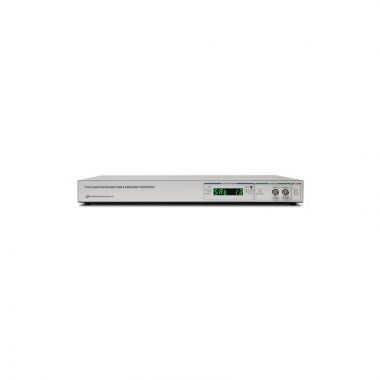
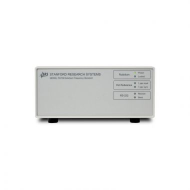
SRS PRS10 Rubidium Frequency Standard
Please contact us for estimated delivery

- Low phase noise < -125dBc/Hz at 10Hz
- Time-tags or phase-locks to a 1 pps input
- 72 hour stratum 1 level holdover
- RS-232 for diagnostics, control and calibration
- Long lamp life and established reliability
- Low cost
Lambda Exclusive Promotion:
Additional 12 months warranty for free (2 years total) via our UK Service Centre.
The device fulfills a variety of communication, synchronisation, and instrumentation requirements. The phase noise of the 10 MHz output is low enough to be used as the reference source for synthesisers. The unit's short-term stability and low environmental coefficients make it an ideal component for network synchronisation. Its low aging rate makes it an excellent timebase for precision frequency measurements.
The Stanford Research Systems PRS10 can time-tag an external 1 pps input with 1 ns resolution. These values may be reported back via RS-232 or used to phase-lock the unit to an external reference (such as GPS) with time constants of several hours. This feature can provide Stratum 1 performance at a very low cost.
The SRS PRS10 establishes a new level of features and performance in atomic frequency standards. Its design provides the lowest phase noise, greatest versatility, and easiest path to system integration of any rubidium frequency standard available.
Operation
All commercial rubidium frequency standards operate by disciplining a crystal oscillator to a hyperfine transition at 6.834,682,612 GHz in rubidium. The amount of light from a rubidium discharge lamp that reaches a photodetector through a resonance cell will drop by about 0.1% when the rubidium vapor in the resonance cell is exposed to microwave power near the transition frequency. The crystal oscillator is stabilised to the rubidium transition by detecting the light dip while sweeping an RF frequency synthesiser (referenced to the crystal) through the transition frequency.
The PRS10 uses a microcontroller, clocked at 10 MHz, to control all aspects of operation and to allow diagnostics, measurement, and closed case calibration via an RS-232 interface. The processor sweeps the RF synthesizer, synchronously detects the optical signal from the physics package, and servos the 10 MHz crystal oscillator to the rubidium transition via a 22-bit DAC and a varactor.
When turned "on", the processor applies a voltage to the varactor corresponding to the last locked value. The frequency-lock servo is disabled until a useful resonance signal is detected from the physics package, providing a smooth transition to the final frequency as the unit warms up. In the case of a problem with the physics package, the unit will suspend the frequency servo and hold the varactor voltage at the last locked value.
Manufacturers of rubidium frequency standards sometimes use a crystal frequency that is an exact sub-multiple of the hyperfine transition frequency in order to simplify the design of the RF frequency synthesiser. Some designs use a DDS synthesizer, clocked by the crystal, to generate the 10 MHz output. Often, the crystal frequency is modulated in order to sweep the synthesiser through the transition frequency. The crystals are usually operated in the fundamental mode and not temperature stabilized. While such approaches are simpler to design, the phase noise, short-term stability, and spur content of their outputs suffer.
In contrast, the 10 MHz output from a PRS10 comes directly from a 3rd overtone, stress-compensated (SC-cut) crystal oscillator operated in an oven at the plateau temperature. A dual-loop RF synthesiser, with a crystal IF at 22.482 MHz, is used to generate 359.72 MHz, and make 6.834 GHz via a step recovery diode. There are several advantages to this approach: the phase noise is very low (<–130 dBc/Hz @ 10 Hz offset), there are no spurious components, and the output will be well behaved should the physics package fail to provide a lock signal. (The aging will be about 5 × 10⁻¹⁰/day when not locked to rubidium.) The phase noise plot of a PRS10 shows a 42 dB reduction in phase noise at 10 Hz offset from the carrier at 10 MHz when compared to a conventional rubidium standard.
Historically, the lifetime of rubidium frequency standards has been dominated by rubidium depletion in the discharge lamp. To avoid excess flicker noise, manufacturers would load less than 100 µg of rubidium into spherical discharge lamps. The PRS10 uses a lamp with a side arm loaded with 1 mg of rubidium. This design eliminates rubidium depletion as a failure mechanism and provides better temperature control without excess flicker noise.
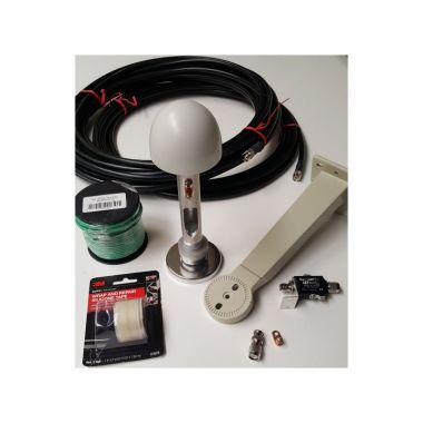
GPS Tracking
Frequency offsets and long-term aging of the PRS10 can be eliminated by phase-locking to a source with better long term stability, such as the 1 pps from a GPS timing receiver. As shown in the Allan variance plot, the short term stability of GPS is poor (about 5,000x10-12) compared to the stability of the PRS10 (about 5x10-12). However, over several hours, GPS is more stable, and so the stability can be improved by phase-locking it to GPS with a long time constant.
The PRS10 can time-tag or phase-lock to a 1 pps input and provide a slewable 1 pps output. The input can be time-tagged with 1 ns resolution, and the result may be read back via the RS-232 interface. When tracking an external input the time constant can be set from 5 minutes to 18 hours.. The 1 pps output may be moved with 1 ns resolution over the range of 0 to 999,999,999 ns via the RS-232 interface.
When an external 1 pps signal is applied the PRS10 will verify the integrity of that input and will then align it's 1 pps output with the external input.The processor will continue to track the 1 pps output to the 1 pps input by controlling the frequency of the rubidium transition with a small magnetic field adjustment inside the resonance cell.
Interface Connector
The interface connector and device form-factor are compatible with Efratom's Model FRS rubidium frequency standard. In its default configuration, the PRS10 uses pins #4 and #7 for the RS-232 interface to provide a complete set of systems diagnostics and control. Internal hardware jumpers allow these pins to be configured as analogue outputs to monitor the lamp intensity and varactor voltage for complete compatibility with the FRS.}
![]() Stanford Research Systems PRS10 datasheet
Stanford Research Systems PRS10 datasheet
![]() Stanford Research Systems PRS10 operation & service manual
Stanford Research Systems PRS10 operation & service manual
![]() Why buying from Lambda makes sense
Why buying from Lambda makes sense