Surface roughness refers to the fine texture of a part’s surface. Every manufactured part’s surface has three key components—form, waviness, and roughness. Together, they influence how well a part performs. The characteristics of these components are tied to the manufacturing process or processes used to create the part. This could be polishing, grinding, cutting, or edging to name a few.
Surface roughness plays a critical role in the functionality and durability of precision components. When a surface is rough, it increases friction between parts, leading to more wear over time. This roughness can also reduce lubrication effectiveness, which can result in faster component degradation and reduced efficiency. Additionally, rough surfaces are more likely to trap dirt or debris, which further accelerates wear and tear.
In some applications, surface roughness can directly impact the lifespan and reliability of the part. For example, rougher surfaces can compromise the sealing effectiveness in components that need to retain fluids or gases, like valves or seals, which may lead to leaks. Roughness also concentrates stress in certain areas, increasing the likelihood of fatigue failure under repeated use.
Beyond functionality, surface roughness affects other factors as well. Rougher surfaces expose a larger area to corrosive elements, which can speed up the corrosion process. This becomes especially critical in environments where parts are exposed to chemicals or moisture. Additionally, in consumer-facing products, excessive roughness can detract from the look and feel of the product, reducing both its aesthetic appeal and perceived quality.
By understanding and controlling surface roughness, manufacturers can ensure that components perform optimally, remain durable, and meet design specifications for both functional and aesthetic purposes.

Form describes the shape of the surface. In other words, is this part flat, spherical, conical, or some combination? Think of waviness as the bridge between form and roughness because it identifies features with longer spacing between them. Roughness is the set of features with the smallest scale and shortest spacing between features.
At first glance, it might seem like a good idea to make a measurement that includes all 3 components. But, in reality, this is somewhat misleading. To get a really good look at surface roughness, first form has to be removed and then the waviness.
How Do You Measure Just the Roughness?
Non-contact, 3D optical profilers with powerful data gathering and data analysis software make this type of measurement easier and faster compared to other roughness inspection methods. A profiler based on Coherence Scanning Interferometry (CSI) makes it possible to collect enough data on most samples while maintaining high vertical precision. The hardware and software make extracting only the roughness data simpler than it may sound. By removing the form and waviness data, we can focus directly on the fine details of roughness.
Start with the Correct Objective
The correct objective is like the proper stylus probe on a contact measurement device. With an objective, paying attention to the following is essential: field-of-view (FOV), working distance, and lateral resolution.
FOV refers to the area the device captures in one image. A larger FOV (lower magnification) shows more of the surface, ideal for general views, while a smaller FOV (higher magnification) captures finer details for in-depth roughness analysis.
Working distance is the space between the lens and the part being measured. It’s essential for keeping a clear focus, especially when the part has protrusions or indentations. This distance prevents damage to both the lens and the part.
Lateral resolution is the device’s ability to distinguish fine details on the surface. High resolution is needed to capture small variations in surface height accurately, helping identify individual roughness features rather than blending them. This type of resolution enables accurate measurement of surface roughness by resolving finer details and height variations.
Continue with a Few Part Setup Considerations
Once the correct objective is installed, it’s time to set up the test part. Profilers like the ZeGage, NewView, and Nexview have a Z-Stop which can be set to prevent a costly crash to the objective, test part, and possibly staging. These Zygo products also have a unique ‘crash prevention’ feature which will minimize or cause no damage to the instrument or the samples, but best practices call for setting the Z-stop before measuring.
With the Z-Stop set, it is time to focus. This can be a manual, two-part process encompassing a visual and interferometric focus. Alternatively, users can utilize Zygo Mx software which offers a convenient Part Finder tool for quickly locating and focusing on the test part. The desired outcome is a sharp and clear image on the monitor, accompanied by the presence of fringes. If there are no fringes, there will be no data.
Even the most carefully positioned test parts will have some degree of tip and tilt present. So, it is important to minimize or eliminate tip and tilt, if possible. This process is often referred to as “leveling the surface” or “nulling the fringes.” This setup consideration is critical to obtaining a good roughness measurement.
At this point, the amount of light might need to be adjusted. Too much light, and the image will be saturated. Too little light, and the image will be very dark. In either case, data will be missing from the final map affecting measurement repeatability.
As mentioned earlier, many of these setup procedures can be simplified by using the Part Finder capability available on all Zygo Optical Profilers. Depending on the objective in use, the user can manually position the objective close to the test part and initiate Part Finder. Another feature, Smart Setup, automatically finds the best focus for the part, adjusts the light level, and sets the optimal measurement length over the field-of-view.
Set the Software Controls
Zygo’s family of 3D Optical Profilers run Mx Software. A set of acquisition controls are available and easy to set. These controls ensure that enough data is acquired to meet the part’s specified precision and throughput requirements.
One of the critical controls that significantly impacts results is scan length. Different surfaces necessitate varying scan lengths. This control refers to the vertical envelope, precisely sized to encompass all of the details of the part in the Z-Axis. Choosing a longer scan length comes at the expense of increased measurement time, so minimizing part tilt can mitigate longer acquisition times. As stated before, if Smart Setup is used, this will be automatically determined and set.
Processing the Measured Data to Isolate Roughness
Data processing is necessary to determine the final roughness parameters after the test part data is acquired. First a Form Remove is applied to the data to remove the overall form of the part (sphere, cylinder, etc.). Next, the data are filtered to remove the waviness from the roughness of the part. For this, a wavelength is carefully chosen to separate the waviness from the roughness. This wavelength is called the cut-off wavelength and is often noted as λc. One thing to note is that these filters are filtering based on the spacing of the features, not the height of the features.
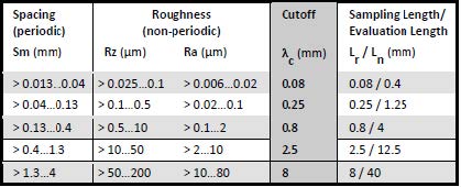
The surface roughness (Ra) call-out on a print should specify the filtering specifications, but if it doesn’t and the drawing is drawn to one of the National Standards formats like ISO and ASME/ANSI, then the filtering controls can be inferred by the call-out. The chart below is an example of a filter cutoff selection chart according to DIN EN ISO 4288, ASME B46.1.
To utilize the chart, first determine which result the specification on the drawing is calling for and then whichever range the result limit falls within, select the corresponding cutoff (λc). For example, if the part drawing had an Ra specification of 0.5µm then a 0.8mm (800 µm) cutoff would be used. The data should be filtered such that the form and waviness have been removed and only the roughness is left.
A Roughness Measurement Example
The following example is a metal sealing surface which can be critical for retaining fluid within a pressure cavity. To capture the roughness and quantify its functional effects, we will need to follow a sequence of processing steps.

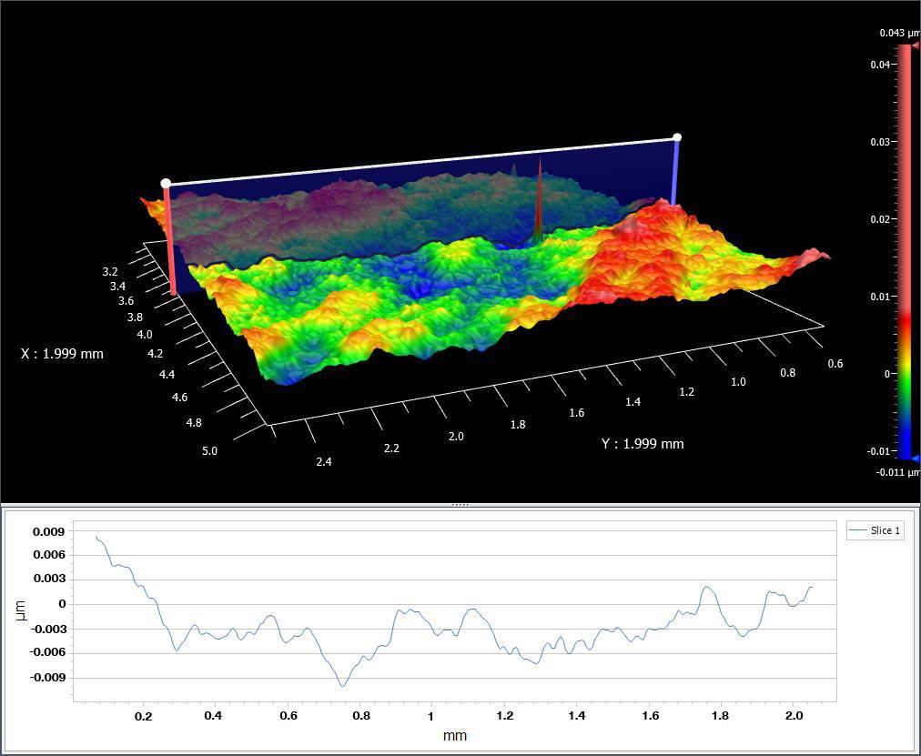
Using the Data Processing Fit/Remove function in Mx and selecting Plane as the Surface Type, removes tilt and fits a plane to the raw data; in essence any shape data is removed.
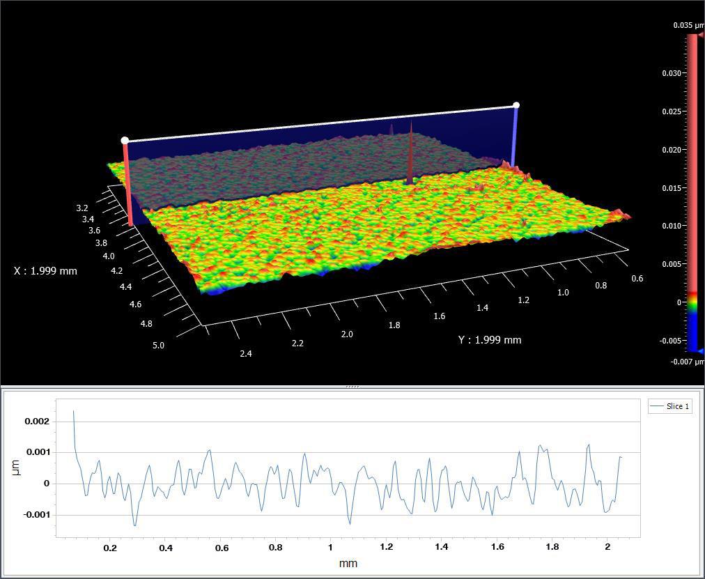
The data is now in a “plane” state. If we apply a high pass filter, per ISO standards, the filter will reveal the surface roughness, as shown above. Waviness has been removed allowing us to see just the roughness components. Note that the ISO standard provides guidance, but you may have to adapt your own filters to relate to the function of your part.
Conclusion
Accurately measuring surface roughness requires a careful approach that separates form, waviness, and roughness. This distinction allows for a more precise assessment of each part’s surface, ensuring it meets performance standards and design specifications. Advanced 3D optical profilers equipped with Coherence Scanning Interferometry (CSI) and smart software solutions make this process both efficient and reliable. By taking advantage of these tools, manufacturers can confidently control surface quality and ensure their products perform at their best. For more on how Zygo’s optical profilers can meet your specific roughness measurement needs, click here.
To speak with one of our Sales & Applications Engineers please call 01582 764334 or click here to email.
Lambda Photometrics is the leading UK Distributor of Characterisation, Measurement and Analysis solutions with particular expertise in Instrumentation, Laser & Light based products, Optics, Electro-optic Testing, Spectroscopy, Machine Vision, Optical Metrology, Fibre Optics, Microscopy and Anti-vibration tables & custom solutions.
-
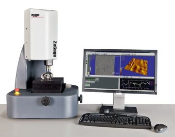
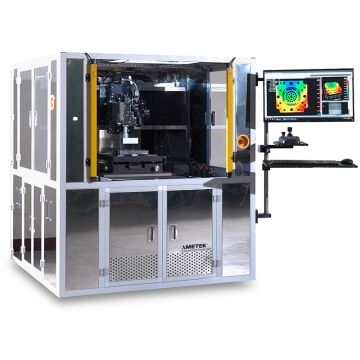
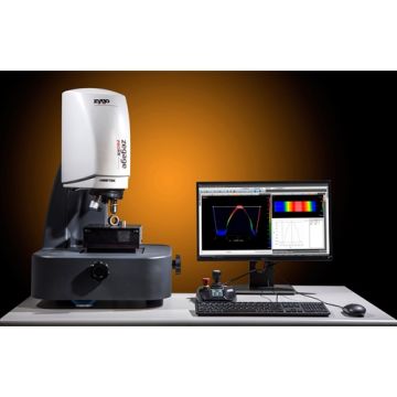
Zygo ZeGage™
This version of the ZeGage is no longer available. It has been superseded by the ZeGage Pro and ZeGage Pro HR. Accessories and objectives are still available.
The ideal non-contact optical profiler for quantitative measurements of 3D form and roughness on precision machined surfaces.
-
Zygo NewView™ 7100
The NewView 7000 and following 8000 series are no longer available. They have been superseded by the NewView 9000 series. Accessories and objectives are still available.
The Zygo NewView 7000 Series of Optical Profilers are no longer available. They have been superseded by the NewView 8000 series, the Nexview and the ZeGage series. Most accessories and objectives are still available.
Zygo NewView 7000 Series Scanning White Light Interferometers (optical surface profiler) for Fast Non contact 3D measurement surface metrology for texture, roughness, flatness, step heights and MEMS device dimensions.
-

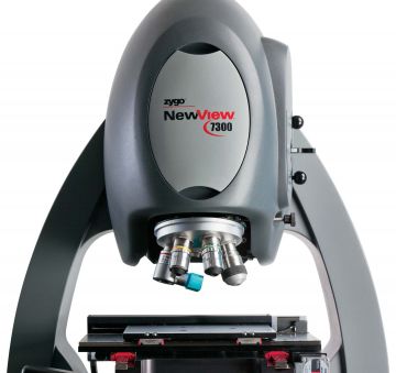
Zygo NewView™ 7300
The NewView 7000 and following 8000 series are no longer available. They have been superseded by the NewView 9000 series. Accessories and objectives are still available.
The Zygo NewView 7000 Series of Optical Profilers are no longer available. They have been superseded by the NewView 8000 series, the Nexview and the ZeGage series. Most accessories and objectives are still available.
Zygo NewView 7000 Series Scanning White Light Interferometers (optical surface profiler) for Fast Non contact 3D measurement surface metrology for texture, roughness, flatness, step heights and MEMS device dimensions.
-
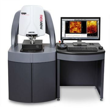
Zygo Nexview™
The Nexview has been superseded by the Nexview NX2. We have a 2018 ex-demonstration Nexview system for sale. Please contact us for more information.
Nexview 3D optical surface profiler excels at measuring all surfaces – from super-smooth to very rough, with sub-nanometer precision, independent of field of view.
-

Zygo NewView™ 8000 Series
The NewView 8000 series is no longer available. It has been superseded by the NewView 9000 series. Accessories and objectives are still available.
Zygo NewView 8000 Series Scanning White Light Interferometers (optical surface profilers) for fast non contact 3D measurement of surface texture, roughness, flatness, step heights and MEMS device dimensions
-

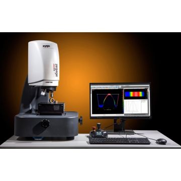
Zygo ZeGage™ Plus
This version of the ZeGage is no longer available. It has been superseded by the ZeGage Pro and ZeGage Pro HR. Accessories and objectives are still available.
The Zygo ZeGage Plus optical profiler expands on the capabilities of the ZeGage profiler with higher precision, faster measurement speed, and an increased range of measurable surfaces – while preserving its ease of use, vibration insensitivity and small footprint.
-

Zygo Nexview™ NX2
For ultra performance and industry-leading speed, precision, and automation. Designed for the most demanding applications. Measure virtually any surface! -

Zygo NewView™ 9000
High performance optical profiler. Well suited for a wide range of applications, and highly configurable to meet your needs! -
Zygo ZeGage™ Pro
Production Ready! Standard performance bench-top optical profiler. Compact design. Simple to use. Measure parts right on the shop floor!
-
Zygo ZeGage™ Pro HR
Production Ready! Standard performance bench-top optical profiler. Compact design. Simple to use. Measure parts right on the shop floor!
-