

Background
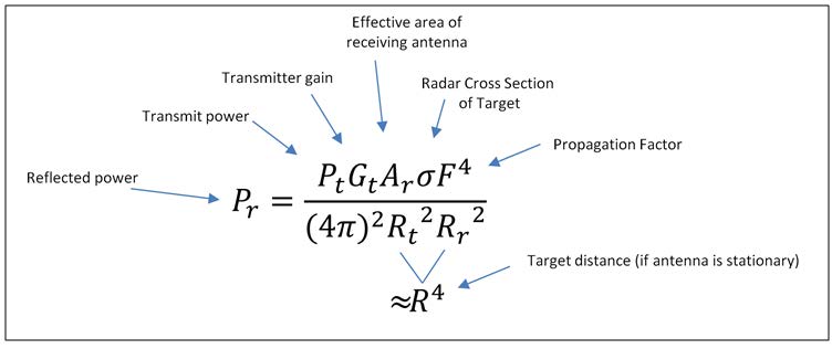
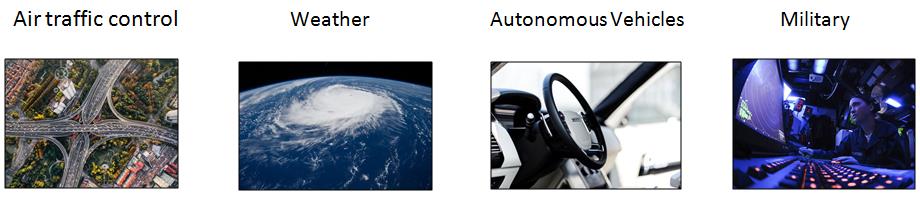
RADAR (“Radio Detection And Ranging”) is a system that uses electromagnetic waves to identify an object, its direction, relative speed, or even for 2D & 3D imaging. Radars help identify both fixed & moving objects such as aircraft, ships, vehicles, weather formations, and terrain. Radars use transmitters that emit electromagnetic waves that are reflected by a target (“Echoes”) and detected by the Radar’s receiver. According to the Radar Equation, the reflected power decreases by the fourth power of the target’s distance:
Radar systems operate in a variety of modes, each with its unique advantages:
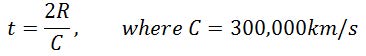
• Pulse radars – This is how Radar first got developed. Basically, you send a short pulse and measure the time it takes to hit the object and to return. This is done repetitively so it could be measured more accurately. Using repetitive pulses, radars save a lot of transmitted power vs the continuous wave radars systems. Using this simple equation, radars can determine the distance of the object:
One way to increase the range of the radar system is to increase the average power of the transmitted signal. Note, the average power includes the downtime when no signal is transmitted. In order to increase the average power it is necessary to increase the duration of the transmitted signal or duty cycle. Therefore, a wider pulse width means a longer operating range.
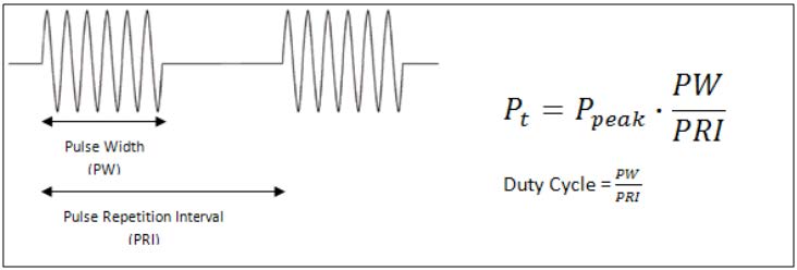
However, the significant drawback of increasing the pulse width is that the resolution of detected targets is compromised. The resolution of the radar system is important in order for the radar to provide a detailed picture of the target. An example of the importance of high resolution is when there are multiple targets. When the pulse width is large the echoes bouncing back from adjacent targets overlap so that to the radar they seem as a single target. Therefore, in order to be able to distinguish between targets, a small pulse width is necessary. However, this will require more peak power in order to maintain the average power of the transmitted signal. Higher peak power makes the design of transmitters and receivers more complex and costly.
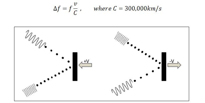
• Continuous Wave – Using continuous-wave (CW) radar, we can measure velocity and direction as well. The speed of a moving object can be measured with precise accuracy using the Doppler-Effect. Basically, it means that if you are transmitting a wave with a certain frequency towards a moving object, the reflected wave is shifted in frequency by an amount which is a function of the relative speed between it and the transmitter-receiver. This shift in frequency can be processed using a technique called Heterodyning:
Heterodyning
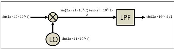
When multiplying two sine signals that have 2 different frequencies, as a product, we will get a sum of two signals. One with the sum of the 2 frequencies and the second with the difference of the two, each of the signals with half the power we had before. This multiplying operation is called Mixing:
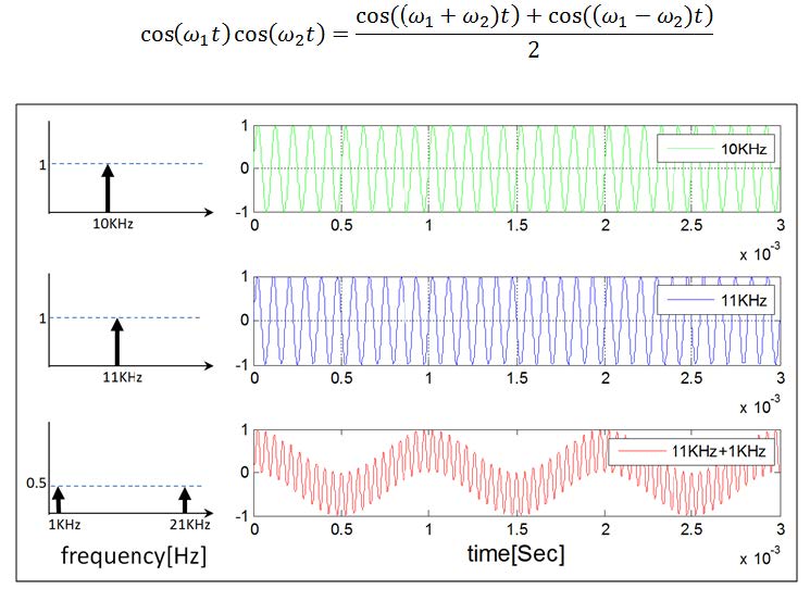
By filtering the unwanted signal (in most cases, the signal with the higher frequency) using a Low Pass Filter, we could get the signal with the difference of the two frequencies:
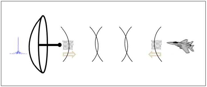
Let us take a simple example of using heterodyning to detect a shift in frequency. If a moving object will come towards a stationary radar system with a certain speed, the reflected wave won’t change its propagation speed (always the speed of light), but the waveform will be compressed in a way so that its frequency will increase:
Radar engineers kept looking to find new and improved ways to get better resolution with longer ranges. One way of achieving better resolution is by transmitting shorter pulses so they won’t overlap. This way, reflected pulses with short durations don’t have a lot of power and might not be detected by the antenna. On the other hand, if the pulses will have long durations, they might be overlapped (for example detecting two objects as one). Another way is to transmit shorter pulses but with a bigger amplitude, in other words, a larger antenna. This method also has its limits with the scalability of the antenna’s size. The solution is to use pulse compression techniques.
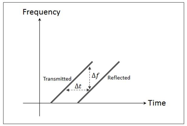
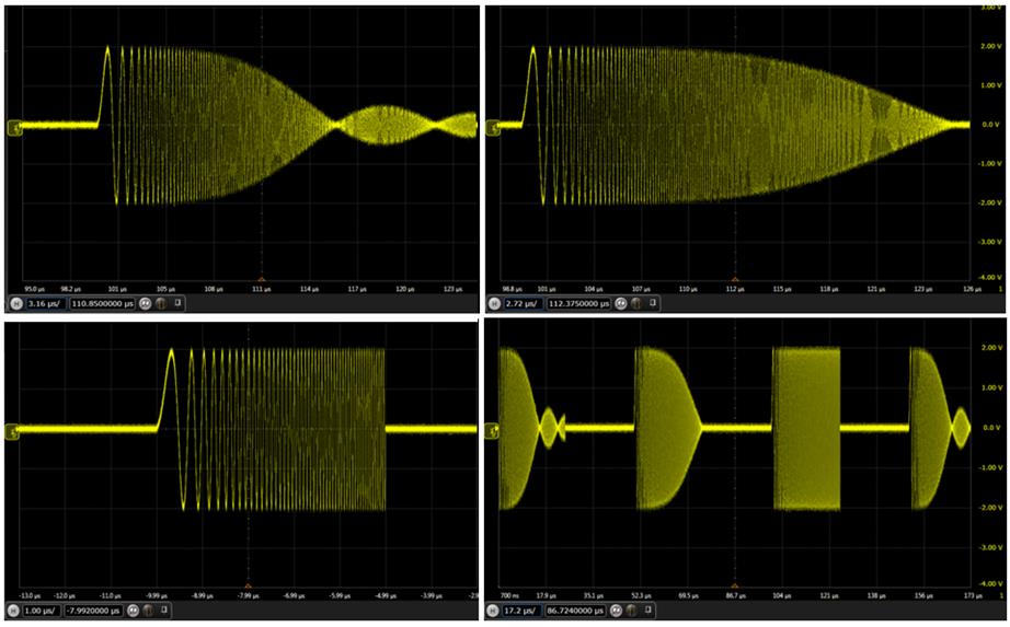
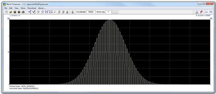
• Pulse Compression – This is how most of our long range radar systems work today. In pulse compression, the phase or frequency of the pulse is changed over time. A popular pulse compression technique is Linear Frequency Modulation (LFM) which is also known as a “Chirp”. This technique allows us to measure both velocity & range of a moving object. Another advantage for using LFM radar signals is that by generating a pulse with a unique start and end frequencies, we are able to differ between two reflected pulses while they overlap at the receiving end (two objects won’t necessarily be identified as one, if the pulses were received at a similar time).

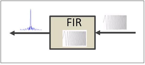
This is done using the correlation function used in Digital Signal Processing to create a Matched Filter, where the filter coefficients are samples of the transmitted chirp pulse. This means that the signals must first be sampled & processed. We could implement such Matched filters using FIR filters, in a way that when the input signal is perfectly lined up with the filter coefficients, we will get a delta function (spike) at its output:
There are a few ways of detecting & monitoring objects using radar systems, here are some examples:
• Scanning - Simply by rotating the radar’s dish towards a moving object.
• Pulsed Doppler Radar – Combines the use of Doppler Effect with using pulse compression in order to increase the probability of detection vs range.
• Stepped Frequency Radar (SFR) – Same as pulsed Doppler radars but with each pulse at a different frequency within the radar’s Detection Bandwidth. This is done to reach higher resolution with lower costs
• Synthetic Aperture Radar (SAR) – SAR radars are following the basic principle: a bigger radar’s dish will result with a finer resolution of space. So in SAR radars, we are taking several coherent measurements of the same reflected signal using several antennas at different places. This is done in a way that you are trying to simulate having a bigger dish.
• Multi antenna beam forming (phased array) – Using several stationary antennas, we could manipulate the phase of several coherent transmitted signals from multiple antennas, in a way that we could detect & follow an object faster and better. After detecting an object, we could set the phase of each transmitted waveform in order to detect the object with max amplitude. This is done by optimizing the superposition of the signals at the object’s current location in space. Another advantage is that there are no moving parts.
Requirement
In order to test & simulate radar systems in a much cost effective way, RF designers & Radar engineers may have different requirements from their test & measurement instrumentation:
Radar Test Signals:
• Pulse/Linear FM (Chirp) pulse
• Frequency Hopping (SFR)
• Binary Phase coded (Barker, Frank, P-code, ZC)
• UWB radar signals
• Continuous Carrier/modulated-Carrier
Measurements:
• Power at 50Ω
• S – parameters
• Noise Figure/SNR
• IP3
• Detection probability/False Alarm probability
• Max Doppler interference
Simulations:
Here are a few examples:
• Phased Array radars systems/SAR - Simulate several Transmitted/Reflected phase coherent signals coming from one or more objects into several antennas.
• Simulate and test using additional interference signals, clutter & terrain interferences.
• Simulate the bandwidth of the radar’s receiver using UWB radar signals
• SFR- Test the radars “Detection Bandwidth” using Frequency hopped pulses, using a number of iterations for each hop.
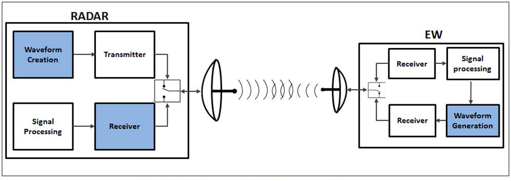
• Electronic Warfare – simulate both Radar’s receiver signals and EW jamming/deception signals.
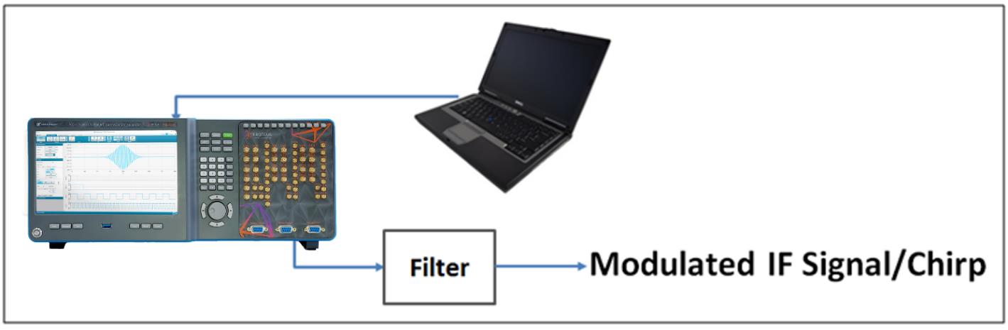
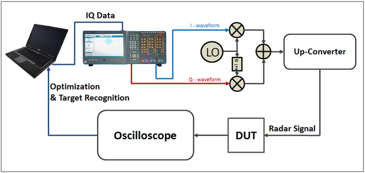
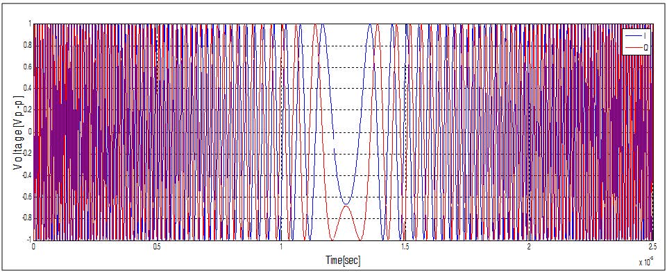
In order to do so, one might need to use an AWG as part of his simulation setup. The AWG should be used to generate baseband I&Q signals for an external modulator for the generation of high frequency signals or using it for direct generation of chirp pulses/continuous waveforms.
The AWG will have to possess the following abilities:
• Arbitrary/Modulation capabilities using a high sampling rate.
• The ability to generate several phase coherent signals, with adjustable phase for each signal. Phase accuracy should be less than 1 degree.
• Low phase noise – Added Doppler shifts should be recognizable (to determine speed).
• A high dynamic range is required, so as not to introduce spurs that can be misinterpreted by the receiver as small targets.
• Sequencing capabilities are required in order to create scenarios for simulation of a
fast dynamic environment using a limited amount of memory.
Solution
Tabor Electronics’ High Speed Arbitrary Waveform Generators (AWGs) serve as an excellent platform for the testing of radar systems. It offers excellent signal quality and dynamic range with a bandwidth of up to 2.5 GHz. Whether used as a standalone unit or combined with the proper Vector Signal Generator, the Tabor AWG can be used as part of the test equipment used to simulate different real scenarios for radar testing.
Tabor Electronics AWGs support the creation of extremely long scenarios, supporting up to 64 million memory points and 32,000 segments. In addition, it supports sequencing (up to 48K steps) and advanced sequencing (sequenced sequences), nesting, looping, and dynamic jumping, thus offering outstanding support for highly complex simulations of real world environment.
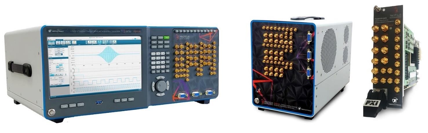
The Tabor Electronics Proteus series of Arbitrary Waveform Generators offers the best performance than any other unit on the market in its price range, featuring:
• Up to twelve channel 1.25GS/s & 2.5 GS/s 16 bit, or dual, four or six channel 9GS/s 16 bit, AWG & AWT configurations
• Integrated NCO for digital upconverting to microwave frequencies
• Real time data streaming directly to the FPGA for continuous and infinite waveform generation
• 9GHz bandwidth, 2.7GS/s 12 bit digitizer option for feedback control system and conditional waveform generation
• Innovative task oriented sequence programming for maximum flexibility to generate any imaginable scenario
• Up to 16GS/s waveform memory with the ability to simultaneously generate and download waveforms
• Excellent phase noise and spurious performance
• User customizable FPGA for demodulation digital filtering and application specific
• Standalone 4U 19'' wide benchtop platform. with 9'' touch display, USB 3.0, 10G Ethernet and thunderbolt high speed interfaces
The Proteus series of AWG enables the generation of extremely long scenarios. With a waveform memory of up to 16GS per channel, with sequence and advance sequence modes, users can define the order and duration of each segment with nesting and looping of stored waveforms. Users can also define when to jump to the following segment with conditional jumping on events.
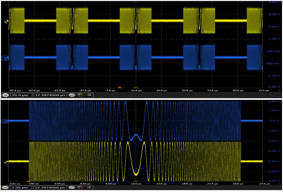
Tabor AWG’s draw Special interest in radar industry due to, excellent low noise performance, controllable channel delay and skew resolution of 10ps, the ability to control & fine tune the amplitude of each outputted channel, and finally the sequencing capabilities that allows two different sequencing tables to be downloaded to each channel with the option of synchronize up to 5 different AWGs (10 synchronized channels).
Chirped pulse sequencing on the Tabor AWG can be created using MATLAB, Python, C++ & LABVIEW or by simply using the ArbConnection, which is a custom made remote control software, provided free of charge by Tabor Electronics.
Applications:
-
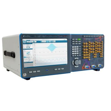
Tabor Proteus 9GHz Arbitrary Waveform Transceiver Benchtop Series
Introducing Tabor’s all new Proteus series, the world’s first Arbitrary Waveform Transceiver. The system integrates the ability to transmit, receive and perform digital signal processing all in a single instrument. The Proteus series comes in a PXIe module, desktop or benchtop platforms. Available in 2, 4, 6 and 12 channel’s from 1.25GS/s to 9GS/s 16 bit AWG & AWT.
The modular, compact and cost effective system offers industry leading performance, various configuration options, an innovative task oriented programming, and user programmable FPGA. So whether it is for Aerospace and Defence, Telecommunications, Automotive, Medical or high-end physics applications Proteus opens the door to a world of infinite possibilities.
Benchtop P1282B Benchtop P1284B Benchtop P1288B Benchtop P12812B Benchtop P2582B Benchtop P2584B Benchtop P2588B Benchtop P25812B Proteus Benchtop P9082B Proteus Benchtop P9084B Proteus Benchtop P9086B
-
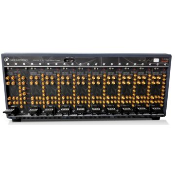
Tabor Proteus 9GHz Arbitrary Waveform Transceiver, PXIe (Gen 3) Series
Introducing Tabor’s all new Proteus series, the world’s first Arbitrary Waveform Transceiver. The system integrates the ability to transmit, receive and perform digital signal processing all in a single instrument. The Proteus series comes in a PXIe module, desktop or benchtop platforms. Available in 2, 4, 6 and 12 channel’s from 1.25GS/s to 9GS/s 16 bit AWG & AWT.
The modular, compact and cost effective system offers industry leading performance, various configuration options, an innovative task oriented programming, and user programmable FPGA. So whether it is for Aerospace and Defence, Telecommunications, Automotive, Medical or high-end physics applications Proteus opens the door to a world of infinite possibilities.
The PXIe (Gen 3) modules offer, space saving, expandability and value for money. Also available in desktop or bench-top platforms, the Proteus series offers industry-leading bandwidth, user-programmable FPGA, and task-oriented sequence programming, delivering maximum flexibility for a variety of complex scenarios.
Industry-leading 4.5 GHz bandwidth for the most cutting-edge applications Real-time streaming via 8 lanes of GEN3 PCIe to supercharge your projects User-programmable FPGA for the most realistic signalling scenarios on the market Compact and affordable form factor, with unlimited PXI expansion for scalability Ability to transmit, receive, and process signals in a single module to simplify integration Task-oriented sequence programming for maximum flexibility to generate complex scenarios.
P1282M, P1284M, P2582M, P2584M, P9082M
-
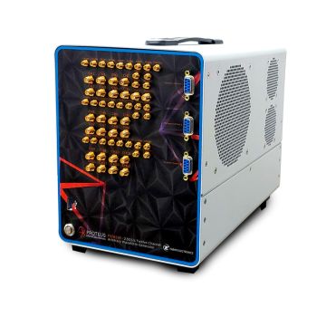
Tabor Proteus 9GS/s Arbitrary Waveform Generator Desktop Series
The desktop version of the Proteus series offers up to 12 channels in a 4U, half 19” dedicated chassis. The compact form size and small footprint saves valuable bench space. Perfect for application in automotive, aerospace, defence, and communications the Proteus Arbitrary Waveform Generator offers the ability to perform real time data streaming and fast feedback loops with an environment dependent waveform generation which will take R&D outcome to a higher level.
The new desktop RF AWG version of the Proteus P948**D series offers up to 12 channels in a 4U, half 19” dedicated chassis. The main difference in these three new models is that they offer an embedded PC with PCIe Gen3 x4 lanes interface as well as the fastest standardized communication interfaces commonly available in PCs today. These include USB3.0 and 10GE interfaces as well as, a thunderbolt 3 interface which enables up to 40Gb/s of data transfer speed. These enable you to easily connect to the Proteus arbitrary waveform transceiver and still offer some of the fastest waveform download available on the market today.
Benchtop P1282B Benchtop P1284B Benchtop P1288B Benchtop P12812B Benchtop P2582B Benchtop P2584B Benchtop P2588B Benchtop P25812B Proteus Benchtop P9082B Proteus Benchtop P9084B Proteus Benchtop P9086B